Thank You For Purchasing The RFID Decoder Test Kit
In this kit we'll focus on the RFID 'decoder'. The decoder looks at the incoming data stream from the RFID receiver and decodes the Manchester data. When a potential valid tag is recognized and audible BEEP is heard as well as RS232 data being sent at 19200 baud that can be interpreted by a PC or another micro.
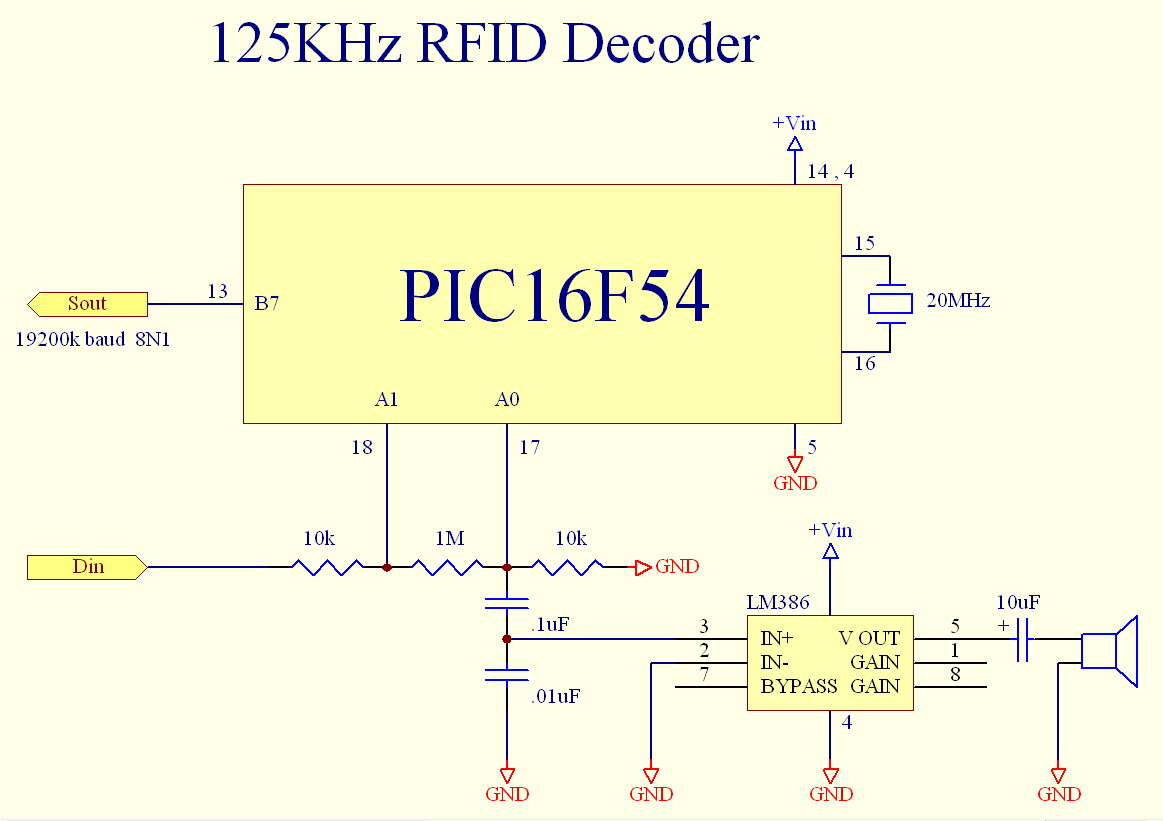
RFID decoder schematic:
RFID decoder Parts List:
x1 8-DIP socket
x1 18-DIP socket
x1 LM386 Audio Amplifier
x1 PIC16F54 (Programmed)
x1 20MHz crystal
x2 10k resistors
x1 1Meg resistor
x1 0.1uF capacitor
x1 0.01uF capacitor
x1 10uF capacitor
x1 Speaker
x2 SIP3 connector
x1 SIP4 connector (two middle connectors removed)
Errata part:
x1 1n4148 diode
Tools you will need:
Soldering Iron
Solder
wire cutters (A spare pair of finger nail clippers works well)
wire strippers
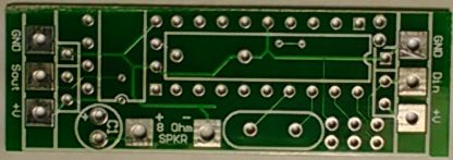
Step 1:
Identify the PCB you will be assembling by the silkscreen printed on the PCB.
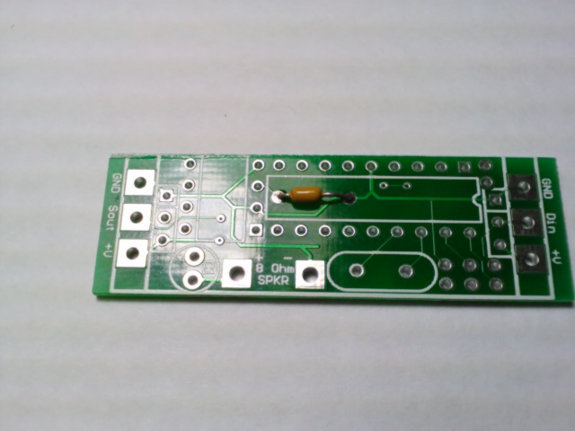
Step 2:
Place the 0.01uF capacitor on the PCB and solder. Trim the excess leads as necessary.
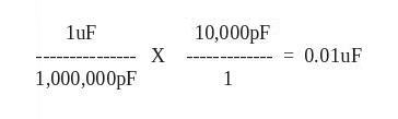
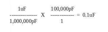
Note: The capacitor will be marked with a 103 ... this can be interpreted as 10 with 3 zeros and referenced in terms of Pico Farads or 10,000pF ... Since there are 1 million pF (pico-Farad) in a uF (micro-Farad) the equation becomes ...
Step 3:
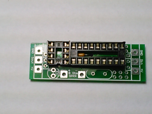
Place the 18-DIP socket and the 8-DIP socket.
Note: Take notice to orient the dimple on the PCB silk screen with the dimple of the physical socket.
Step 4:
Place the 0.1uF capacitor on the PCB and solder. Trim the excess leads as necessary.
Note: The capacitor will be marked with a 104 ... this can be interpreted as 10 with 4 zeros and referenced in terms of Pico Farads or 10,000pF ... Since there are 1 million pF (pico-Farad) in a uF (micro-Farad) the equation becomes ...
Step 5:
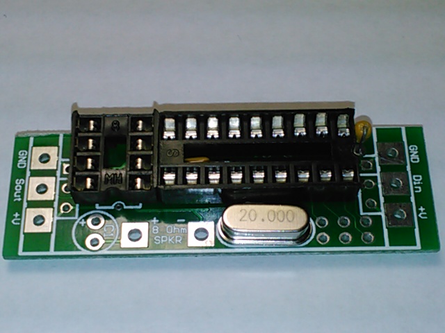
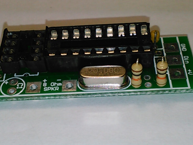
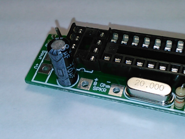
Place the 20MHz crystal on the PCB and solder. Trim the excess leads as necessary.
Step 6:
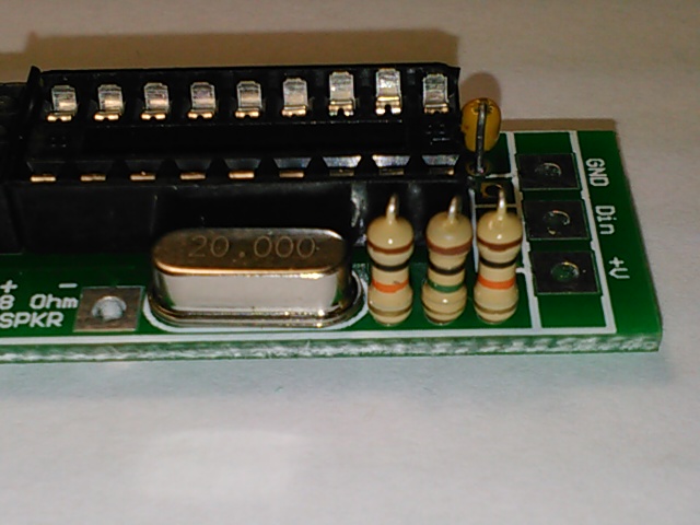
Place the 10k resistors (Brown-Black-Orange) on the PCB and solder. Trim the excess leads as necessary.
Step 7:
Place the 1 Meg resistor (Brown-Black-Green) on the PCB and solder. Trim the excess leads as necessary.
Step 8:
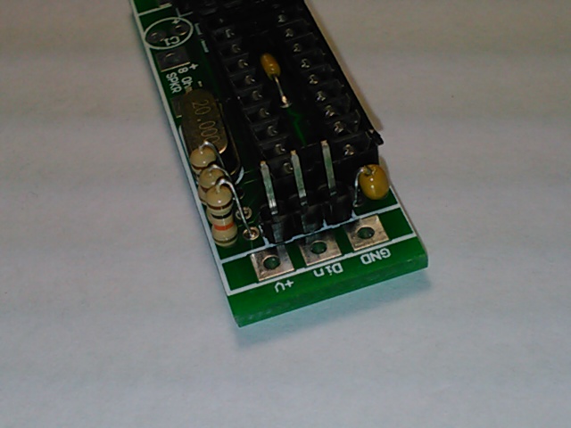
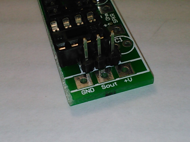
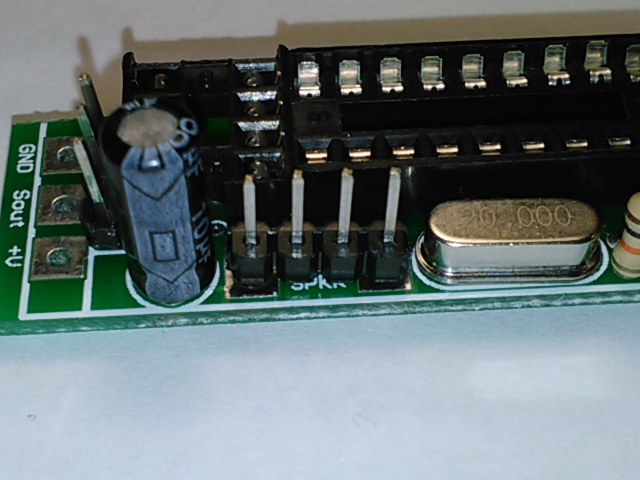
Place the SIP3 headers on the PCB and solder.
Step 9:
Place the 10uF capacitor on the PCB. Trim the excess leads as necessary. Note: Capacitors have a polarity with the negative terminal usually indicated. Observe the polarity on the silkscreen (indicated with a '+' for the positive terminal)
Step 10:
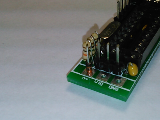
Place the SIP4 header on the PCB and solder.
Step 11:
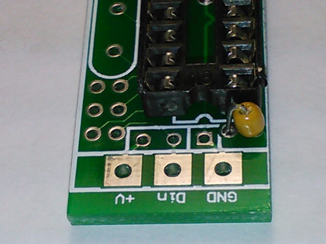
Place 1n4148 diode on the PCB and solder.
Note: Diodes have a polarity. The side with the “band” indicates the Cathode, while the side without the “band” indicates the Anode. The Anode should be soldered to the V+ of the board in this case.
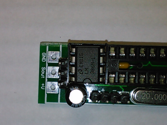
Step 12:
Carefully insert the LM386 into the socket. Make Note of where the dimple on the IC is in relation to the socket.
Make sure that all of the pins of the IC are aligned with the socket and gently press the IC into the socket. This may require some slight bending of the IC pins in order to achieve proper positioning.
Step 13:
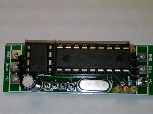
Carefully insert the PIC16F54 IC into the socket. Make Note of where the dimple on the IC is in relation to the socket.
Make sure that all of the pins of the IC are aligned with the socket and gently press the IC into the socket. This may require some slight bending of the IC pins in order to achieve proper positioning.
Step14:
Plug the Speaker into the 4 pin SIP.
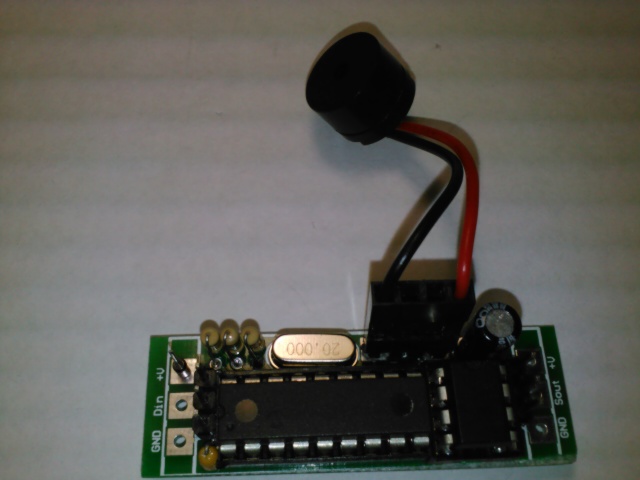
Step15:
Congratulations!!! You have completed all three parts of this kit, you have the RFID 'tester' ready to go.