Thank You For Purchasing The RFID Exciter Test Kit
In this kit we'll focus on the RFID 'exciter'. The exciter simply provides the 125kHz energy to power a standard 125kHz passive RFID tag in the absence of an actual door reader so that we have a signal for the RFID detector circuit to work with. Optionally you can use an actual RFID door reader.
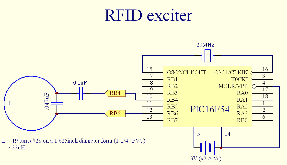
RFID exciter schematic:
RFID exciter Parts List:
x1 0.1uF Capacitor
x1 18 pin DIP socket
x1 20MHz crystal
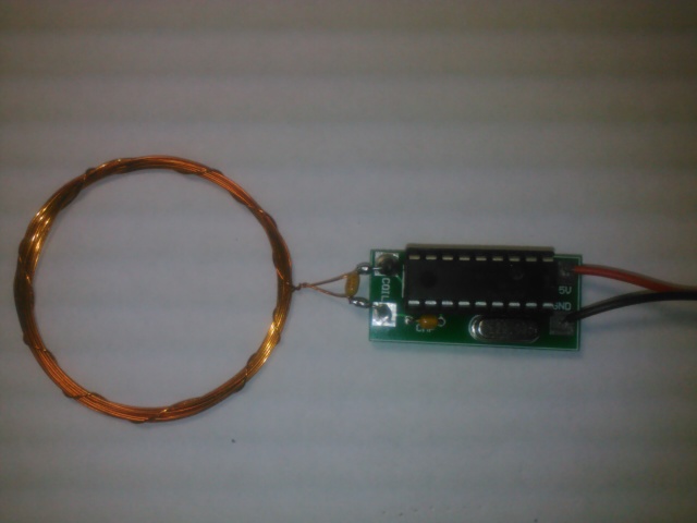
x1 33uH Coil with 0.047uF Capacitor
x1 Dual AA battery holder
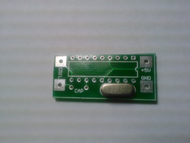
x1 PCB board
x1 PIC16F54 (Programmed)
Tools you will need:
Soldering Iron
Solder
wire cutters (A spare pair of finger nail clippers works well)
wire strippers
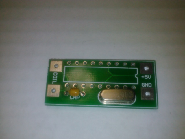
Step 1:
Place the 20MHz crystal on the PCB and solder. Trim the excess leads as necessary.
Step 2:
Place the 0.1uF Capacitor on the PCB and solder. Trim the excess leads as necessary.
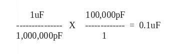
Note: The capacitor will be marked with a 104 ... this can be interpreted as 10 with 4 zeros and referenced in terms of Pico Farads or 100,000pF ... Since there are 1 million pF (pico-Farad) in a uF (micro-Farad) the equation becomes ...
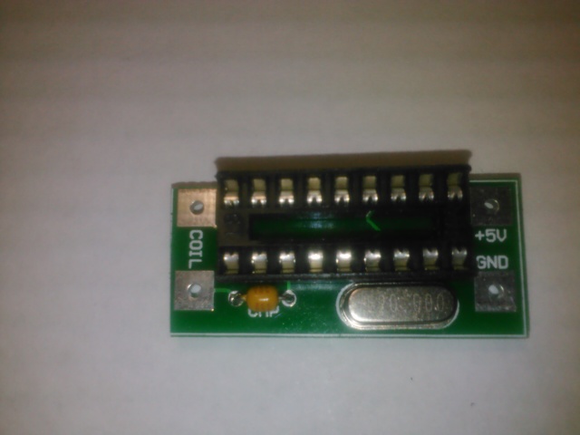
Step 3:
Place the 18-DIP socket on the PCB and solder.
Note: Take notice to orient the dimple on the PCB silk screen with the dimple of the physical socket.
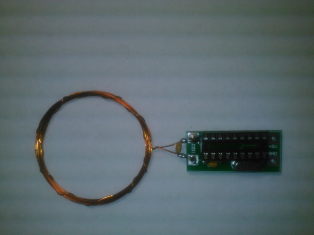
Step 4:
Place the 33uH Coil/Capacitor on the PCB and solder. Trim the excess leads as necessary.
Note: The 33uH Coil and 0.047uF Capacitor form a resonant LC tank tuned to approximately 125kHz.
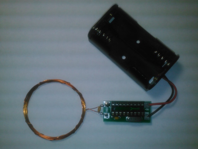
Step 5:
Place the Battery holder on the PCB and solder. Trim the excess leads as necessary.
Note: The PCB says +5V, this is a maximum voltage level, the minimum voltage is about 2V.
The AA battery pack provides 3V to the unit. The BLACK lead goes to GND, and the RED lead goes to the pad labeled +5V.
Step 6:
Carefully insert the PIC16F54 IC into the socket. Make Note of where the dimple on the IC is in relation to the socket.
Make sure that all of the pins of the IC are aligned with the socket and gently press the IC into the socket. This may require some slight bending of the IC pins in order to achieve proper positioning.
Step 7:
Congratulations!!! You are ready to apply power, but WAIT, hold that thought you don't have anything to listen to your creation just yet. Proceed to the next part of the kit where we will build the RFID receiver.