Connecting the Modules together: Making it work
In this part of the instruction we will focus on connecting all of the RFID component boards together. The RFID receiver, the RFID Decoder, and connecting it to the (already made board) USB to TTL converter.
First Identify each of your boards:
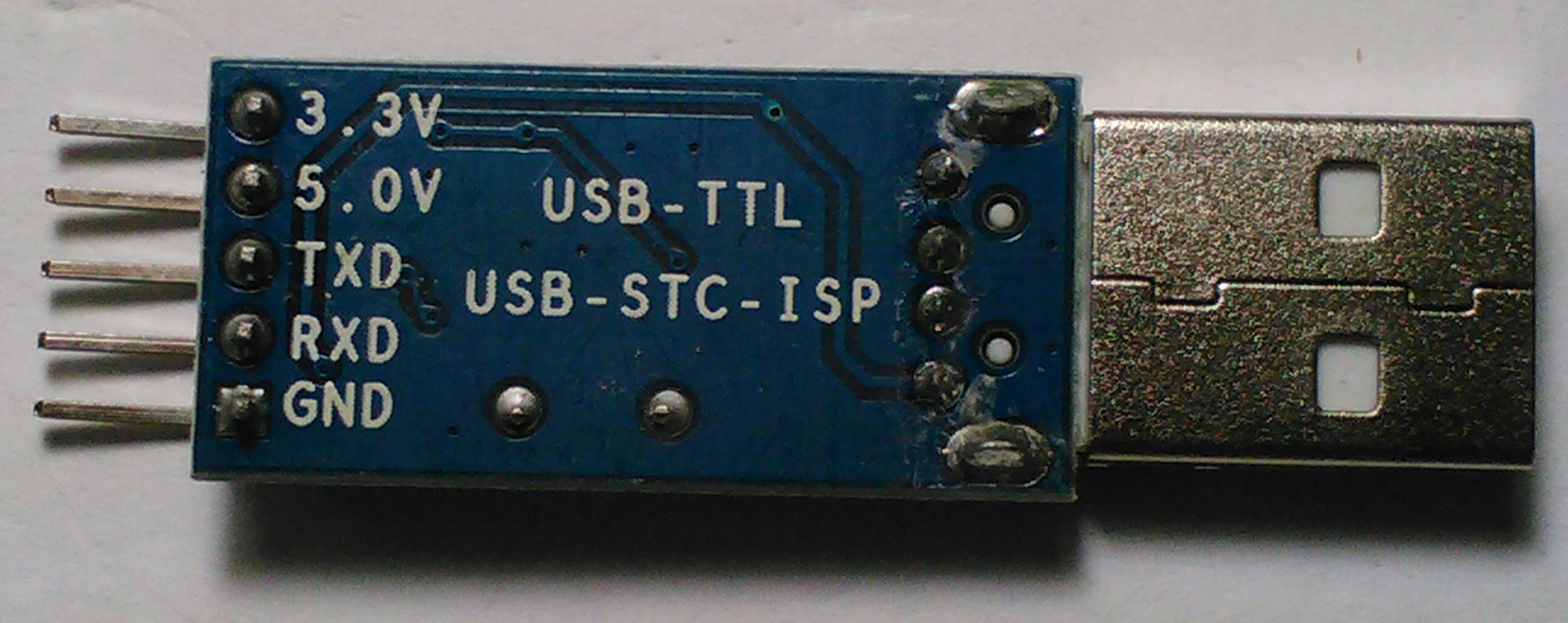
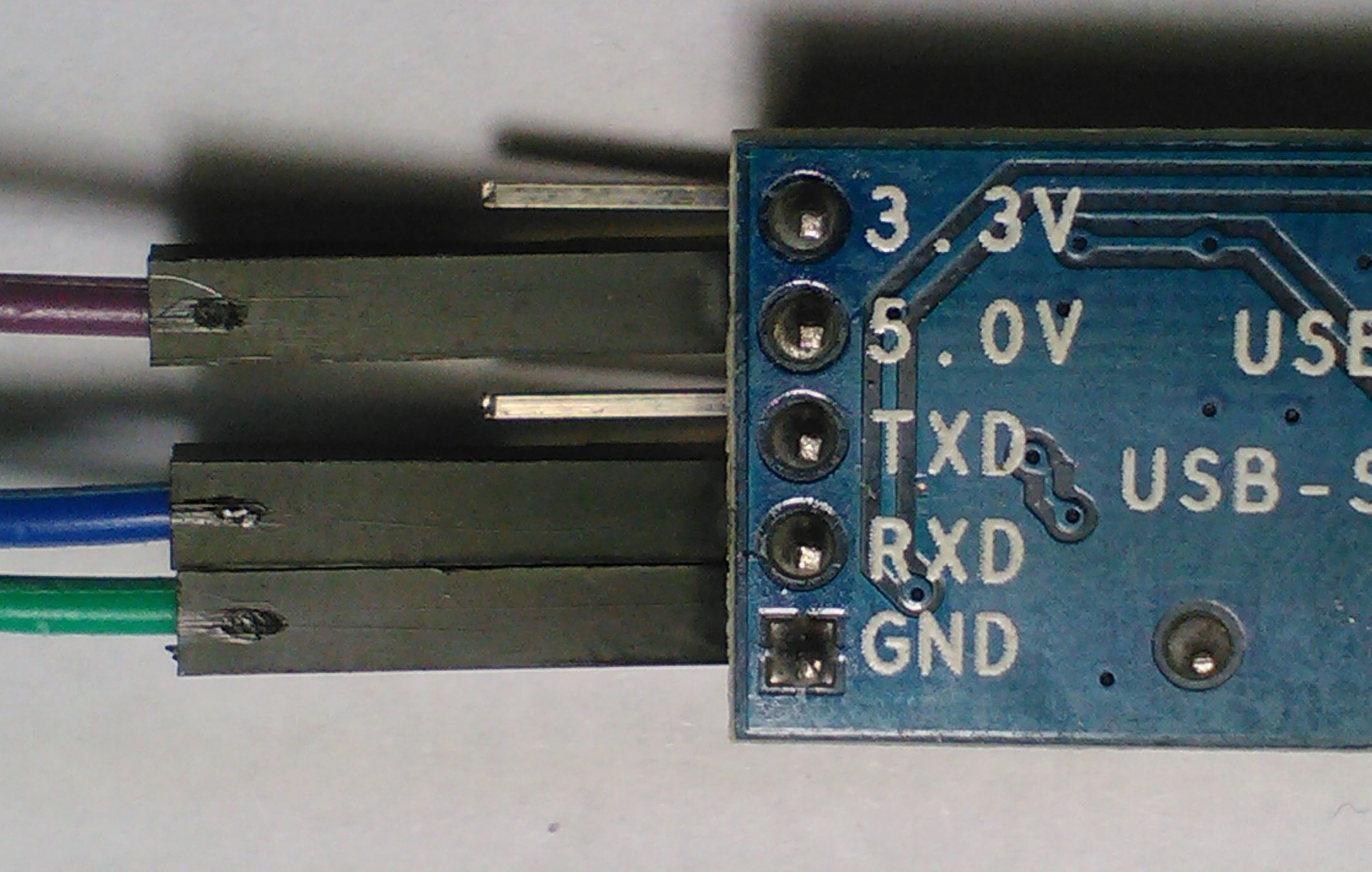
USB2TTL converter:
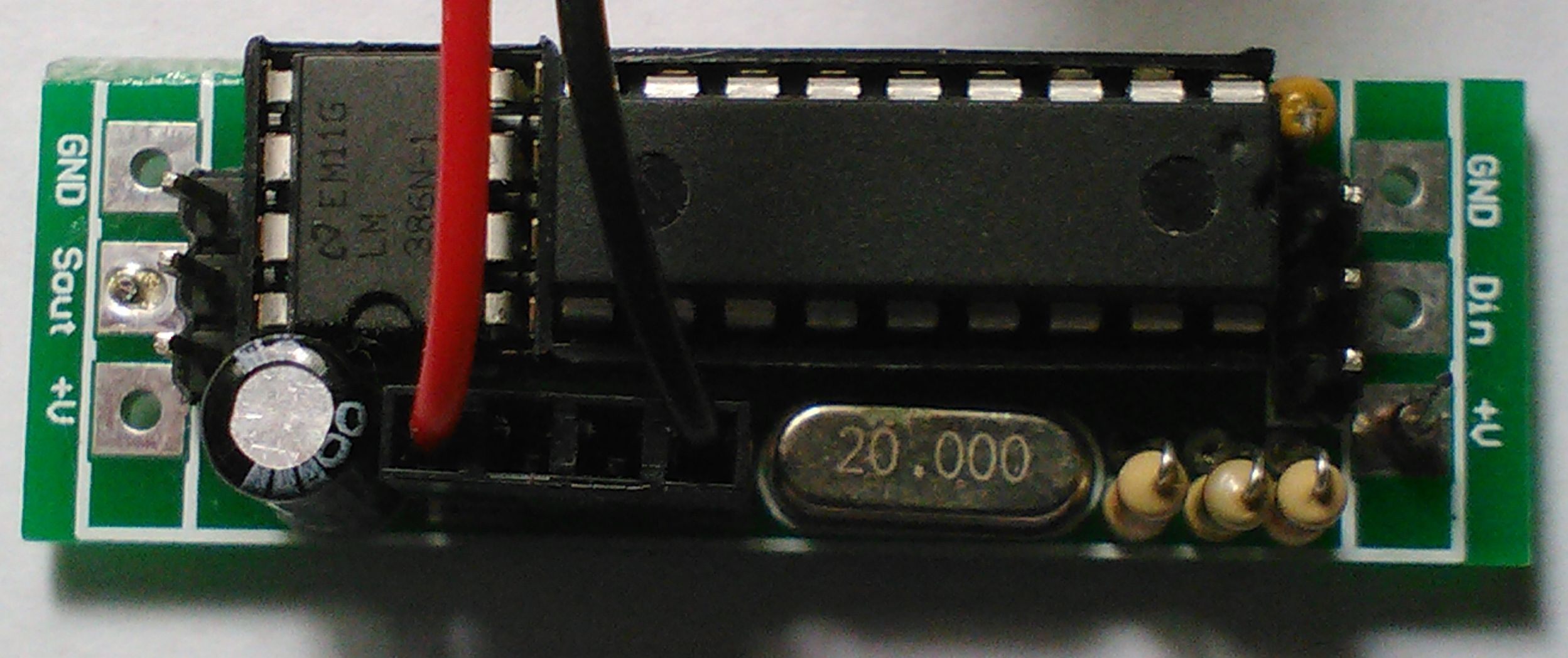
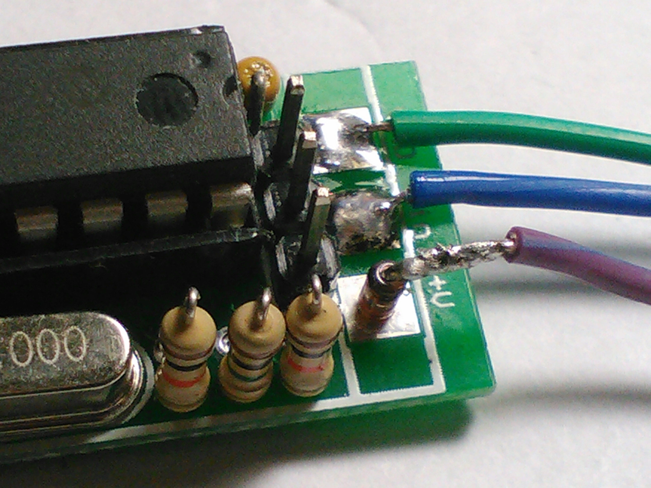
Decoder Board:
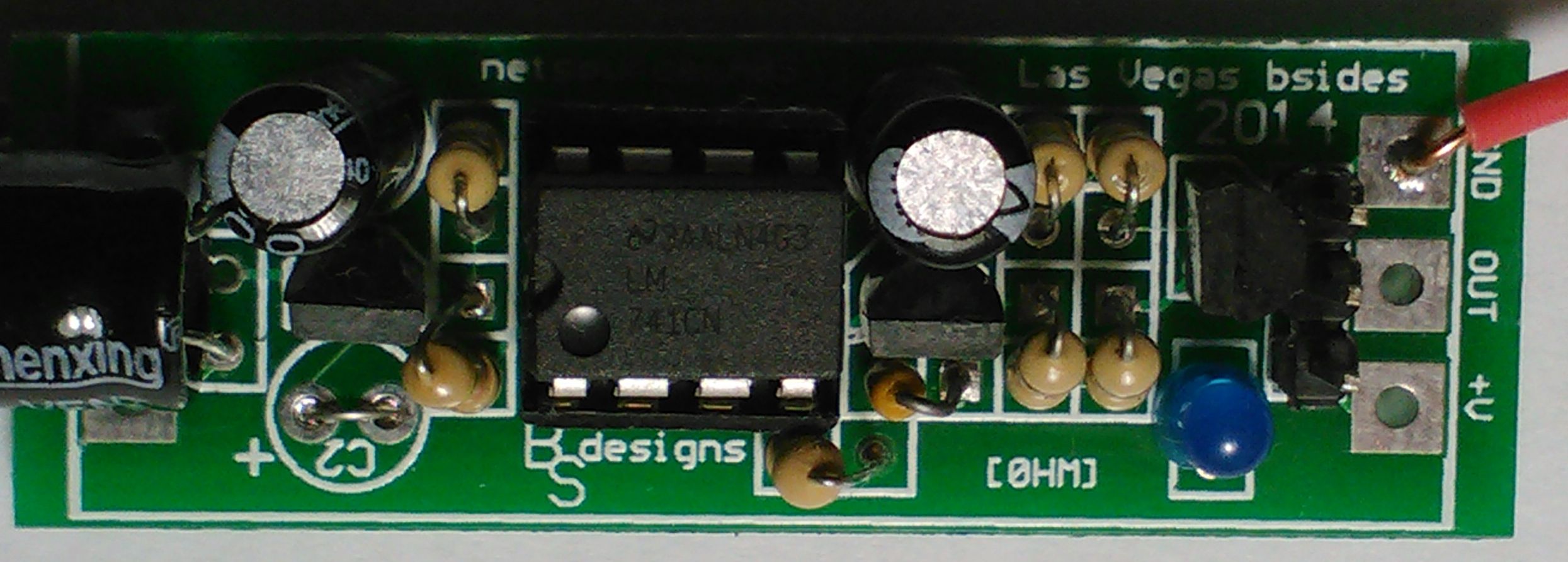
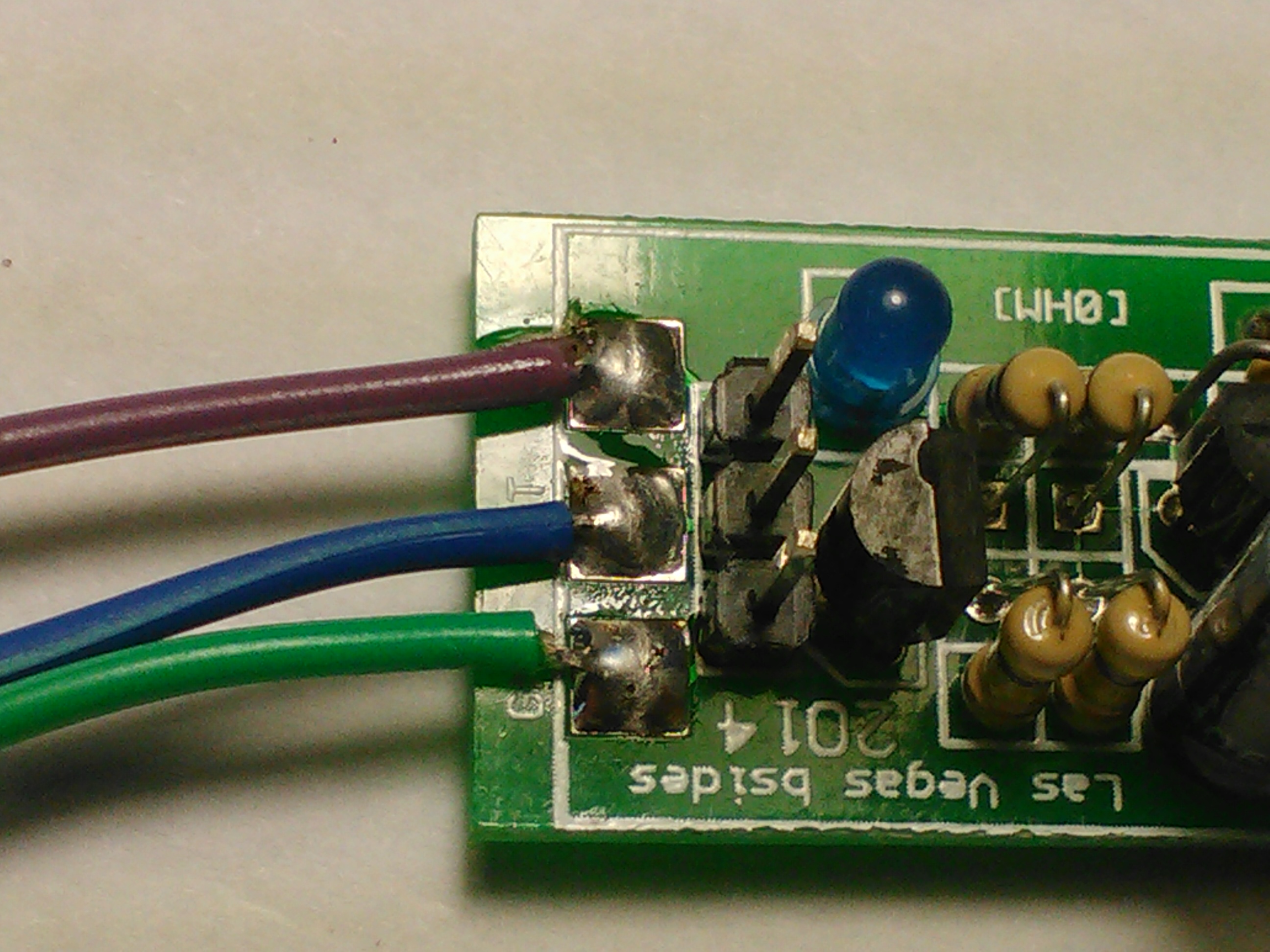
Receiver Board:
...Also, there are 7 wire connectors, 4 with a female pin connector on one end, and 3 plane wires. You will want to pay close attention to these, since the color codes do not match. You will just need to pay attention to the actual connection and ignore the color.
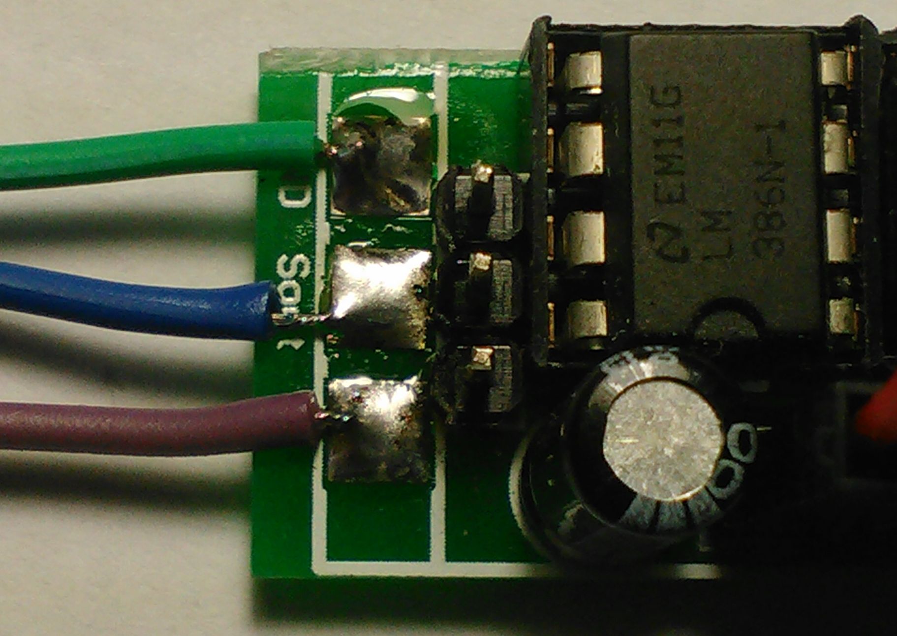
Step 1:
Use 3 female pin connectors on the Decoder board and solder the wire end to GND, Sout, and V+. Keep track of the colors that were used. In my case of this demo Green(GND),Blue(Sout),Purple(V+).
Step 2:
On the USB2TTL board connect the GND from the Decoder to the GND on the USB2TTL, connect the Sout from the Decoder to the RXD on the USB2TTL, connect the V+ on the Decoder to the 5.0V on the USB2TTL.
Step 3:
Use 3 connector wires on the Decoder board and solder the wire end to GND, Sin, and to the diode connected to V+. Use caution and avoid prolonged heat when soldering to the diode. Again keep track of the colors that were used. In my case of this demo Green(GND),Blue(Sin),Purple(V+ diode connection).
Step 4:
On the Receiver Board connect the GND from the Decoder to the GND on the Receiver, connect the Din from the Decoder to the OUT on the Receiver, connect the (V+ diode connection) on the Decoder to the +V on the Decoder.
Step 5:
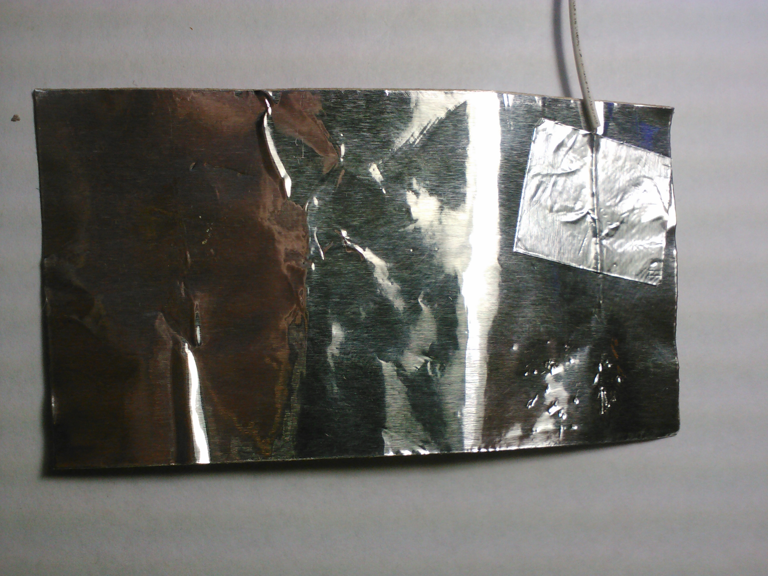
WE NEED A SHIELD. As with most things RF related, shielding is usually required. There is no exception to the rule here, a shield is required on the receiver board. To do this we are using a piece of aluminum foil adhesive commonly found at a hardware store, used for air conditioner conduit repairs. The piece that we are using only needs to be the size of a business card. Two other squares (about 1 square inch) of adhesive foil are also included. Use one of them to attach the remaining female pin connector wire end to the foil.
Step 6:
On the Receiver Board connect the GND to the shield connector. Again keep track of the colors that were used. In my case of this demo a White wire is used for the shield connection.
Step 7:
Wrap the shield around the Receiver with the foil side facing outward, use the remaining 1 inch square of foil to secure the wrapped foil.
Step 8:
Running the DEMO software. I wrote a software DEMO to communicate with the Decoder's output, using FREE BASIC COMPILER. I have tested this on a my Linux machine as well as some others, I have not tested it in Windows, but it should still compile and work properly.
Serial Communication Specs over USB2TTL connector:
8N1 19200 baud
Data Stream:
$FF:$FF:${D0}:${D1}:${D2}:${D3}:${D4}
$FF:$FF are the SYNC bytes and always read $FF:$FF
$D0 to $D4 contain the 10-Bit RFID code in Hexadecimal
Note1:
On the Linux (Fedora) the USB2TTL evaluates to /dev/ttyUSB0 this can vary from computer to computer depending on what you have plugged in. You can determine where your plug evaluates to by typing ...
dmesg | grep attached
...in a terminal window.
Note2:
For proper permissions you may need to chmod /dev/ttyUSB0 for READ on some systems as a root user.
Here is a screen shot of the DEMO code reading a tag:
On the far right a log is kept of the last 30 unique tags that were scanned. If a tag is already in the log list (repeated) it will be highlighted in green within the list. The program only adds a new tag to the list if the last decoded tag is not currently on the list. The matrix shows a visual representation of the current decoded tag.
Step 9:
Congratulations!!! Yes, this time we are done. Thanks again for your patience and Purchase.